
| Version 5 (modified by maronga, 8 years ago) (diff) |
|---|
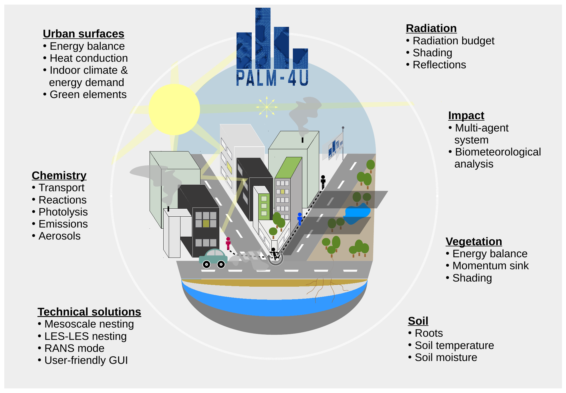
PALM-4U components
PALM-4U is frequently referred to as a separate model for the simulation of urban atmospheric boundary layers. However, from a technical point of view, PALM-4U are special components that have been developed to suit the needs of modern academic urban boundary layer research and practical city planning related to the urban microclimate and climate change. PALM-4U components are shipped with PALM and are available after installation of PALM. PALM-4U components are thus also available in PALM and might be used without being limited to urban area applications. Per definition, starting from PALM version 5.0, the user runs PALM-4U as soon as buildings are placed within the model domain.
The PALM-4U components are have been and will be further developed by a consortium of institutions within the framework of the funding programme "[UC²] - Urban climate under change", funded by the German Federal Ministry of Education and Research (BMBF). For more information, see http://uc2-mosaik.org.
In the following an overview of the PALM-4U components is given. Note that some of these still undergo major changes and improvements at the moment. A final documentation and publications are planned in 2018 and 2019.
Topography parameterization
The Cartesian topography in PALM is generally based on the mask method (Briscolini and Santangelo, 1989) and allows for explicitly resolving solid obstacles such as buildings and orography. The implementation makes use of the following simplifications:
- the obstacle shape is approximated by (an appropriate number of) full grid cells to fit the grid, i.e., a grid cell is either 100% fluid or 100% obstacle,
- the obstacles are fixed (not moving).
Topography is realized in 3-D, e.g., overhanging structures as for example bridges, ceilings, or tunnels, are allowed, i.e. topography does not necessarily be surface-mounted. If no overhanging structures are present, the 3-D obstacle dimension reduces to a 2.5-D topography format, which is conform to the Digital Elevation Model (DEM) format (DEMs of city morphologies have become increasingly available worldwide due to advances in remote sensing technologies). In case of overhanging structures, however, 3-D topography information is required to mask obstacles and their faces in PALM.
The model domain is then separated into three subdomains:
- grid points in free fluid without adjacent surfaces, where the standard PALM code is executed,
- grid points next to surface that require extra code (e.g., surface parametrization), and
- grid points within obstacles, where the standard PALM code is executed but multiplied by zero.
Additional topography code is executed in grid volumes of subdomain B. The faces of the obstacles are always located where the respective surface-normal velocity components u, v, and w are defined so that the impermeability boundary condition can be implemented by setting the respective surface-normal velocity component to zero.
In case of 5th-order advection scheme, the numerical stencil at grid points adjacent to obstacles would require data which is located within the obstacle. In order to avoid this, the order of the advection scheme is successively degraded at respective grid volumes adjacent to obstacles, i.e., from the 5th-order to 3rd-order at the second grid point above/beside an obstacle and from 3rd-order to 1st-order at grid points directly adjacent to an obstacle.
Simulations with topography require the application of MOST between each surface and the first computational grid point outside of the topography. For vertical and horizontal downward-facing surfaces, neutral stratification is assumed for MOST.
In the PALM core, buildings are primarily realized as obstacles that react to the flow dynamics via form drag and friction forces by assuming a constant flux layer between the building surface and the adjacent air volume. A simple thermodynamic coupling is also possible by prescribing surface fluxes of sensible (and latent heat) at any of the building surface grid elements.
The technical realization of the topography and treatment of surface-bounded grid cells is be outlined in Section topography implementation.
Urban and natural surface schemes
In order to simulate interactions between the atmosphere and the soil-vegetation continuum, an energy balance solver for natural surfaces in urban environments is essential to predict realistic surface conditions and fluxes of sensible heat and latent heat. When using the concept of the surface skin layer, where vegetation and bare soil fractions are considered to be flat and have a joint skin layer temperature, T skin , the energy balance reads dT skin C skin
Rn − H − LE − G ,
dt (3.1) where Cskin is the heat capacity of the skin layer, Rn is the net radiation at the surface, H and LE are the tur- bulent surface fluxes of sensible and latent heat, and G is the heat flux into (or out of) the soil. Fluxes are de- fined positive (negative) when they are directed away (towards) the surface. A full interactive land surface scheme (LSM) was recently implemented in PALM, based on the Tiled European Centre for Medium-Range Weather Forecast Scheme for Surface Exchange over Land (Balsamo et al., 2009, TESSEL/HTESSEL, e.g.) and was first applied by Maronga and Bosveld (2017). The scheme consists of an energy balance solver for T skin and a multi-layer soil scheme that takes into ac- count the vertical diffusion of heat as well as vertical water transport in the soil. Vegetation is fully parameter- ized, including root extraction of water from particular soil layers used for transpiration and a prognostic equa- tion for the liquid water stored on plants by interception. So far, however, all vegetation is treated to be subgrid- scale, e.g. the canopy has no vertical extent and is pa- rameterized by aerodynamic parameters such as rough- ness lengths and heat capacity and conductivity of the skin layer. The land surface scheme is also applied for paved surfaces, which only deviates in the treatment of vegetated surface by different material properties and imperviousness to water.
In order to simulate realistic urban environments, an adapted version of the land surface parameterization is available for building facade elements. Essentially, this involves the solution of an adapted version of Eq. 3.1 for each urban surface element, such as build- ing facades, roofs and impervious horizontal surfaces like pavement. For solving Eq. 3.1, the radiative transfer in the urban canopy, including multiple reflections and shading from buildings must be calculated, which may be considered to be one of the main challenging tasks in urban surface modelling (see Sect. 3.1.7). In order to estimate the heat flux G into the material, all building facades must be coupled to a multi-layer wall model. This is further complicated by the fact, that facades can not only consist of solid walls, but usually also consist of significant fractions of windows and sometimes green elements. Windows in particular have significantly dif- ferent physical properties than solid (greened) wall, e.g. in albedo, and they also allow shortwave radiation to en- ter the building. A preliminary version of an urban surface model (USM) has been recently entered the PALM default code (Resler et al., 2017), which already includes an energy balance solver for solid walls (see Fig. 5). In the course of MOSAIK we will take this as a basis to add the treatment of windows and green facades using the tile approach. Also, we will couple the USM to an indoor climate and energy demand model (see Sect. 3.1.6).
RANS turbulence parameterization
Radiative transfer in the urban canopy layer
- refer to radiation models in PALM
Indoor climate model
Chemistry module
Multi-agent system
External forcing by COSMO data
- refer to PALM overview's "external forcing" page and vice versa
Data input, output, and handling
- Coupling to the water balance model STORM for preprocessing of soil moisture
- Analysis tools and direct output of biometeorological quantities
soon.
Attachments (7)
-
PALM-4U_logo.png
(438.9 KB) -
added by maronga 8 years ago.
PALM-4U Logo
-
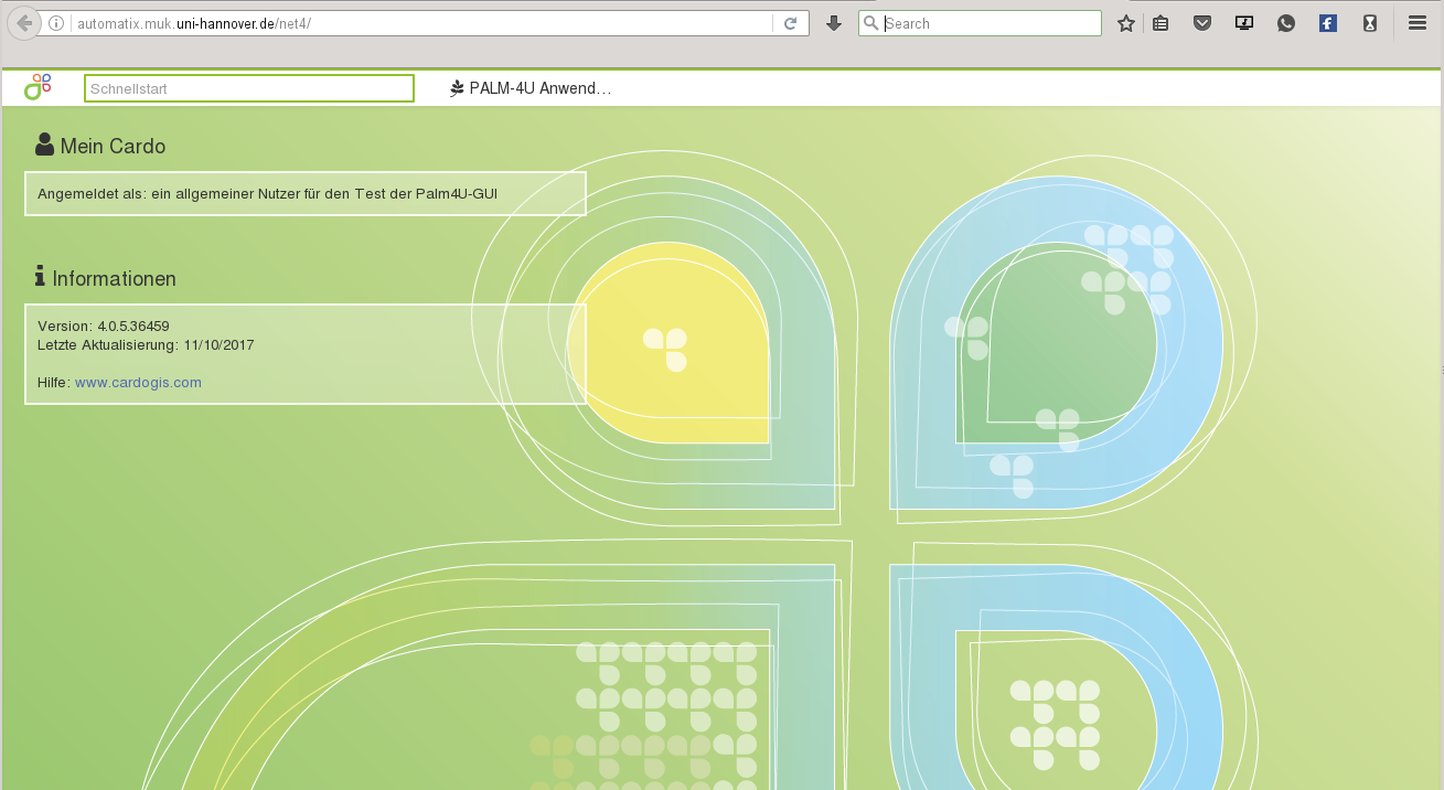
PALM-4U_gui.png
(194.6 KB) -
added by maronga 8 years ago.
PALM-4U GUI example image
- skizze_mosaik.odg (471.9 KB) - added by kanani 6 years ago.
- skizze_mosaik_plus_text.odg (471.1 KB) - added by kanani 6 years ago.
- skizze_mosaik_plus_text.pdf (2.8 MB) - added by kanani 6 years ago.
- skizze_mosaik.pdf (240.2 KB) - added by kanani 6 years ago.
- skizze_mosaik_plus_text.png (442.8 KB) - added by kanani 6 years ago.