
| Version 5 (modified by suehring, 8 years ago) (diff) |
|---|
Topography implementation
Under construction
With revision -r2232, the topography implementation is completely revised. Starting from this revision, overhanging structures (e.g. bridges, ceilings or tunnels) are allowed, i.e. topography does not necessarily be surface-mounted.
The topography implementation described in Sect. boundary conditions allows the use of 2-D topography height data (if no overhanging structures should be considered), or 3-D topography information. The topography input data has to be provided within a rastered ASCII or NetCDF file. Rastered 3-D topography consists of values either 1 (within topography) or 0 (outside topography), and has to be provided up to the level of the highest present topography structures. After reading and mapping of topography data to the 3-D grid in PALM, flag arrays are set in order to mask grid boxes within the integration loops accordingly.
The prognostic terms are executed overall, i.e. also within topography. Masking of topography is done via Fortran integer bit flags, where a certain bit position indicates whether the respective grid point belongs to an obstacle (bit is 0) or to the atmosphere (bit is 1). Different bit positions indicate different masking on the staggered grid, e.g. on the u, v, w grid, equivalent to the former nzb_u/v/w_inner arrays. Further, regions where special wall-bounded code is executed, is also masked via special bit flags. A list of the respective bit flags and their meaning concerning the deprecated implementation via the nzb_u/v/w_inner arrays can be found in Table 1.
| Bit position | Meaning |
|---|---|
0 | mask topography on scalar-grid ( former nzb_s_inner ) |
1 | mask topography on u-grid ( former nzb_u_inner ) |
2 | mask topography on v-grid ( former nzb_v_inner ) |
3 | mask topography on w-grid ( former nzb_w_inner ) |
8 | mask regions where surface-bounded code for u, v, w, and scalars is executed ( combines information of former nzb_s_outer, nzb_u_outer, nzb_v_outer and nzb_w_outer arrays ) |
9 | mask regions where model-top fluxes are applied ( former nzt_diff ) |
12 | flags upward-facing surfaces on scalar-grid |
13 | flags downward-facing surfaces on scalar-grid |
14 | flags upward-facing surfaces on u-grid |
15 | flags downward-facing surfaces on u-grid |
17 | flags upward-facing surfaces on v-grid |
17 | flags downward-facing surfaces on v-grid |
18 | flags upward-facing surfaces on w-grid |
19 | flags downward-facing surfaces on w-grid |
20 | mask topography on u-grid and one grid point above, used only for adding random perturbations ( former nzb_u_inner+1 ) |
21 | mask topography on v-grid and one grid point above, used only for adding random perturbations ( former nzb_v_inner+1 ) |
24 | mask regions where surface-bounded code is executed on scalar-grid ( former nzb_s_outer ) |
25 | mask regions where surface-bounded code is executed on scalar-grid ( former nzb_s_outer+1 ) |
26 | mask regions where surface-bounded code is executed on u-grid ( former nzb_u_outer ) |
27 | mask regions where surface-bounded code is executed on v-grid ( former nzb_v_outer ) |
28 | mask regions where surface-bounded code is executed on w-grid ( former nzb_w_outer ) |
29 | mask regions where surface-bounded code is executed on s-grid ( former nzb_diff_s_outer - 1 ) |
30 | mask regions where surface-bounded code is executed on s-grid ( former nzb_diff_s_outer ) |
The following example illustrates the general realization of topography masking in the code using Bit flags:
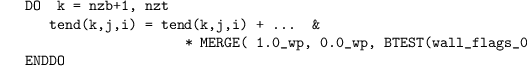
Here, the intrinsic Fortran function MERGE returns 1 if wall_flags_0(k,j,i) at bit position zero is 1 (BTEST returns .TRUE.), else, MERGE would return 0 and no term is effectively added to the tend array. A similar approach is also realized for the 5th-order advection-scheme to degrade the order near surfaces.
they can be directly incorporated into the standard loop structure of the Fortran code as lower vertical index
for all integration loops. Therefore, PALM employs two 2-D height index arrays (e.g., nzb_w_inner(j, i) and nzb_w_outer(j, i) for the velocity component w) to separate the domain into four regions based on the vertical index k (see Fig. 4 in Sect. boundary conditions):
![\begin{itemize}
\item[A.] \texttt{0 $\leq$ k} $<$ \texttt{nzb\_w\_inner}, grid points
within obstacles or in the ground that are excluded from
calculations,
\item[B.] \texttt{nzb\_w\_inner} \texttt{$\leq$} \texttt{k} $<$
\texttt{nzb\_w\_outer}, grid points next to vertical walls, where
wall-bounded code is executed,
\item[C.] \texttt{k} $=$ \texttt{nzb\_w\_inner} $=$
\texttt{nzb\_w\_outer}, grid points next to horizontal walls, where
wall-bounded code is executed,
\item[D.] all other $k$, grid points in free fluid.
\end{itemize}](/trac/tracmath/51c939794396b365677a5f953f1d9decb01a2036.png)
The additional topography code is executed in regions B and C only. As the velocity components are defined on a different (staggered) grid
than the scalar quantities (see Fig. 1 in Sect. discretization), three extra pairs of 2-D height index arrays are defined; two for the horizontal velocities and one for scalar quantities (e.g., nzb_s_inner and nzb_s_outer for scalar quantities).
Treatment of holes
In case there are holes in the topography that are resolved by only one grid point, the topography array in filtered so that such holes are filled up to the minimum topography height of the directly adjoining grid points in the x- and the y-direction. This is necessary, because for such chimney-like features resolved by one grid point, the continuity equation is not fulfilled on a discrete grid, as the only degree of freedom for the pressure solver is the vertical. Such holes are suspected to lead to unrealistic velocity blow-ups, hence, they are filled up.